画像をダウンロード system block diagram 360763-Communication system block diagram
Block diagram A block diagram is a visual representation of a system that uses simple, labeled blocks that represent single or multiple items, entities or concepts, connected by lines to show relationships between them An entity relationship diagram (ERD), one example of a block diagram, represents an information system by showing theThus it is always better to draw the block diagram of the system in the easiest possible way thereby making the analysis simple But as we also know that the block diagram representation of a system involves summing points, functional blocks, and takeoff points connected through branches and flow of signal shown by the arrowheadsBlock diagrams to the rescue Block diagrams visually represent a system To show how they work, here are a few difference equations with corresponding block diagrams Delay 1/2 yn=(xnxn −1)/2 averaging filter Delay yn=yn −1xn account with 0% interest Pause to try 13 Draw the block diagram for the endowment ac

Automotive Braking System Block Diagram Electronic Products
Communication system block diagram
Communication system block diagram-Draw block diagram of basic electronic communication system and state the function of each block Answer i) Input signal The information can be in the form of sound, picture or data coming from computerBlock Diagram in control systems Any system can be described by a set of differential equations, or it can be represented by the schematic diagram that contains all the components and their connections However, these methods do not work for complicated systems The Block diagram representation is a combination of these two methods


Physical Block Diagram
A system block diagram is a high level modularization of the system that separates the overall system into maximally decoupled subsystems System block diagrams enable one to visualize the system as large interacting components that can be conceptualized and developed independentlyA block diagram makes a very efficient representation of the overall running of a computer system It displays the necessary processes needed to get the desired output from a computer from the input you feed into at the start In the diagram below, the control unit (CU) and the arithmetic & logic unit (ALU) make up the Central Processing Unit (CPU) in a computer It is the brain cum the heart1 Block Diagram Reduction Techniques Prepared by, AParimala Gandhi, AP(SS)/ECE Department, KIT/CBE CONTROL SYSTEM ENGINEERING 2 Block diagram Transfer Function Ratio between transformation of output to the transformation of input when all the initial conditions are zero A Block diagram is basically modelling of any simple or complex system
Interactive Block Diagrams Our Interactive Block Diagram tool is as easy to use as 1, 2, 3 With a vast variety of diagrams to choose from, you are able to experience the full breadth of the ON Semiconductor product portfolio in a clear, concise mapped out system level block diagramFor the system at rest, the system input produces on the system output the signal given by which is symbolically represented in Figure 46 using a block diagram H(s) F(s) Y(s)=H(s)F(s) Figure 46 An openlooptransfer function Note that the above block diagram can also be used in the case when the system initial conditions are different from zeroBlock Diagram in Contol System By using block diagrams when examining larger systems, attention can be focused on a smaller number of elements or subsystems whose properties may already be knownBy doing this, a set of individual blocks representing the various elements or subsystems is formed, and these blocks are interconnected to represent the whole system
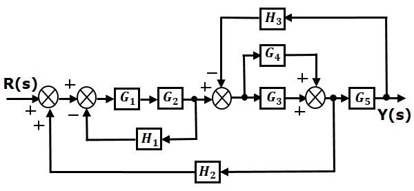
Here is a list of best free block diagram maker software for WindowsThese software simplifies the process of creating a block diagram as they come with various block shapes and connecting linesAccording to the system, you can use various types of blocks like Rectangle, Oval, Circular, etc Usually, rectangle boxes (blocks) are used to represent the main parts of a system and directionalHowever, while reducing the block diagram it is to be kept in mind that the output of the system must not be altered and the feedback should not be disturbed So, to reduce the block diagram, proper logic must be used Hence for the reduction of a complicated block diagram into a simple one, a certain set of rules must be appliedIn this tutorial we shall learn about block diagrams in control systems A block diagram is an intuitive way of representing a system It is a graphical representation that shows us how the systems are interconnected and how the signal flows between them In other words, block diagrams are mathematical drawings of the system
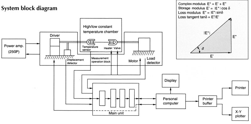


System Block Diagram
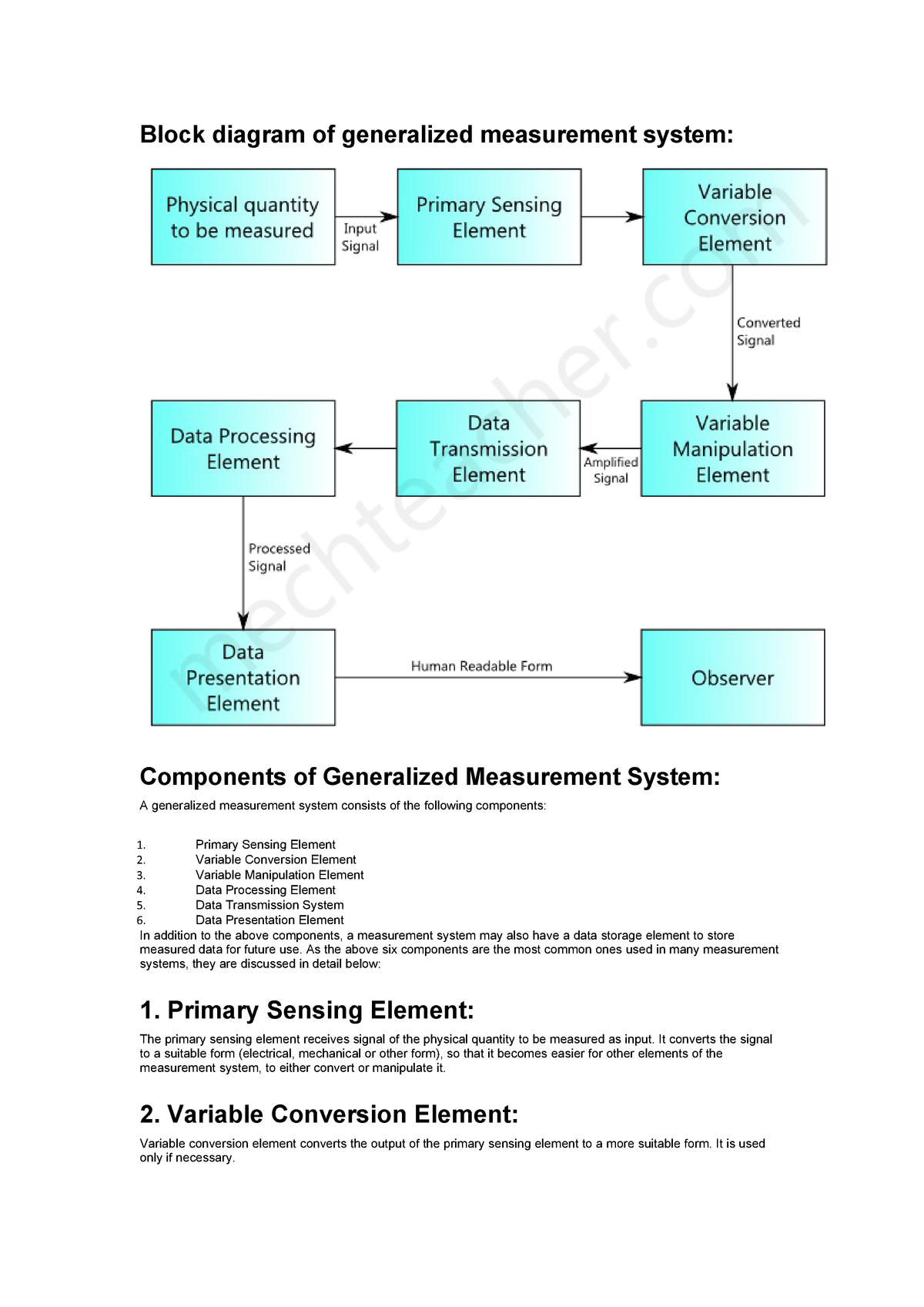


Block Diagram Of Generalized Measurement System Block Diagram Of Generalized Studocu
In this tutorial we shall learn about block diagrams in control systems A block diagram is an intuitive way of representing a system It is a graphical representation that shows us how the systems are interconnected and how the signal flows between them In other words, block diagrams are mathematical drawings of the systemBlock Diagram Modeling of SecondOrder Systems INTRODUCTION Block diagrams are a method of describing the behavior of a dynamic system In a block diagram, each discrete component, or block, represents part of the system These blocks are connected together, representing how the "signal" flows between components This can aid inThe block diagram example "Document management system architecture" was created using the ConceptDraw PRO diagramming and vector drawing software extended with the Block Diagrams solution from the area "What is a Diagram" of ConceptDraw Solution Park


Closed Loop System And Closed Loop Control Systems


File System Block Diagram 3 Jpg Wikiversity
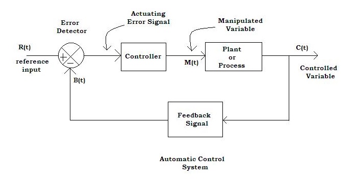
The block diagram example "Document management system architecture" was created using the ConceptDraw PRO diagramming and vector drawing software extended with the Block Diagrams solution from the area "What is a Diagram" of ConceptDraw Solution ParkBlock diagram – process control system Plant or Process Plant or process is an important element of process control system in which variable of process is to be controlledBlock Diagram of Computer and Explain its Various Components By Dinesh Thakur A computer can process data, pictures, sound and graphics They can solve highly complicated problems quickly and accurately Input This is the process of entering data and programs in to the computer system


Cray 2 System Block Diagram Chm Revolution


Engineering Education Control System Block Diagram 8 Download Scientific Diagram
For the system at rest, the system input produces on the system output the signal given by which is symbolically represented in Figure 46 using a block diagram H(s) F(s) Y(s)=H(s)F(s) Figure 46 An openlooptransfer function Note that the above block diagram can also be used in the case when the system initial conditions are different from zeroThe block diagram reduction process takes more time for complicated systems Because, we have to draw the (partially simplified) block diagram after each step So, to overcome this drawback, use signal flow graphs (representation)Hi friends, In this article, I am going to discuss the data acquisition system block diagram, function of each block, and its applications This article will provide you an overview about data acquisition system in simple words Data acquisition system is a computerized system that collects data from the real world, converts it into the form of electrical signals and do required processing on


Block Diagram Of Electronic Engine Management System


Block Diagram Of Electromechanical Systems Dc Motor Dademuchconnection
Block Diagram in Contol System By using block diagrams when examining larger systems, attention can be focused on a smaller number of elements or subsystems whose properties may already be knownBy doing this, a set of individual blocks representing the various elements or subsystems is formed, and these blocks are interconnected to represent the whole systemBlock diagram shown in Figure 344 Figure 346 Block diagram of a system Solution The block diagram of Figure 344 can be modified to that shown in Figure 345(a) Eliminating the minor feedforward path, we obtain Figure 345(b), which can be simplified to that shown in Figure 35(c)The transfer function C(s)/R(s) is thus given byBlock Diagram What is a Block Diagram?


Drone Quadcopter


Block Diagram Of Digital Control System Electrical Engineering
Block Diagram of Computer System The Computer system consists of mainly three types that are central processing unit (CPU),Input Devices, and Output DevicesThe Central processing unit (CPU) again consists of ALU (Arithmetic Logic Unit) and Control Unit The set of instruction is presented to the computer in the form of raw data which is entered through input devices such as keyboard or mouseBlock Diagram of Computer and Explain its Various Components By Dinesh Thakur A computer can process data, pictures, sound and graphics They can solve highly complicated problems quickly and accurately Input This is the process of entering data and programs in to the computer systemBlock Diagram Modeling of SecondOrder Systems INTRODUCTION Block diagrams are a method of describing the behavior of a dynamic system In a block diagram, each discrete component, or block, represents part of the system These blocks are connected together, representing how the "signal" flows between components This can aid in


Pdf 3 2 Block Diagram Components Of Motion Control System Semantic Scholar


Closed Loop Control System Block Diagram Types Its Applications
Block Diagram Reduction Figure 1 Single block diagram representation Figure 2 Components of Linear Time Invariant Systems (LTIS) Figure 3 Block diagram components Figure 4 Block diagram of a closedloop system with a feedback element BLOCK DIAGRAM SIMPLIFICATIONS Figure 5 Cascade (Series) ConnectionsDynamic Systems – Block Diagrams Block Diagram Representation Summing Junction–Used to sum signals together ∑ x1 − − x3 x2 x1 −x2 −x3 Constant Gain–Scalar multiplier k x1 kx1 ms cs k 1 2 f(t) x(t) Transfer Function–Gvein a system with zero initial conditions, the transfer function is the ratio of output due to inputA block diagram is a specialized flowchart typically used by engineers to provide a visualization of systems and their various interactions Block diagrams are ideal for creating a highlevel overview of a system to account for major system components, visualize inputs and outputs, and understand working relationships within your system


System Dynamics And Control Module 13c Example Block Diagram Reduction Youtube


File System Block Diagram Jpg Wikiversity
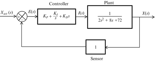
Block Diagram Representation of Electrical Systems In this section, let us represent an electrical system with a block diagram Electrical systems contain mainly three basic elements — resistor, inductor and capacitor Consider a series of RLC circuit as shown in the following figure Where, V i (t) and V o (t) are the input and output voltages Let i(t) be the current passing through the circuitA block diagram of this system is shown in Fig 11 You have been given the task of designing the compensation Begin by considering a proportional control law D c (s) = K Figure 11 Control system for Problem 633 (a) Use MATLAB to draw a Bode plot of the openloop system for D c (s) = K = 1Optical Fiber Communication System Block Diagram Sreejith Hrishikesan September 28, 19 General Light Wave System Communication systems that use high carrier frequencies in the near IR region of visible spectrum are called optical communication systems or general light wave systems Light wave system that employs optical fibre as channel for


Physical Block Diagram


Block Diagrams
Here is a list of best free block diagram maker software for WindowsThese software simplifies the process of creating a block diagram as they come with various block shapes and connecting linesAccording to the system, you can use various types of blocks like Rectangle, Oval, Circular, etc Usually, rectangle boxes (blocks) are used to represent the main parts of a system and directionalA block diagram is a specialized, highlevel flowchart used in engineering It is used to design new systems or to describe and improve existing ones Its structure provides a highlevel overview of major system components, key process participants, and important working relationshipsA block diagram is a graphical representation of a system – it provides a functional view of a system Block diagrams give us a better understanding of a system's functions and help create interconnections within it Block diagrams derive their name from the rectangular elements found in this type of diagram


System Block Diagram For Firmware Architecture By Novo Engineering Novo Engineering
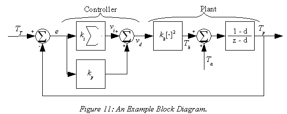


Wescott Design Services Using Block Diagrams
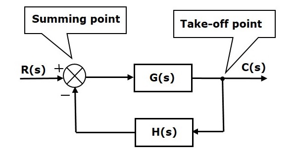
Interactive Block Diagrams Our Interactive Block Diagram tool is as easy to use as 1, 2, 3 With a vast variety of diagrams to choose from, you are able to experience the full breadth of the ON Semiconductor product portfolio in a clear, concise mapped out system level block diagramA block diagram is a diagram of a system in which the principal parts or functions are represented by blocks connected by lines that show the relationships of the blocks They are heavily used in engineering in hardware design, electronic design, software design, and process flow diagrams Block diagrams are typically used for higher level, less detailed descriptions that are intended to clarify overall concepts without concern for the details of implementation Contrast this with the schematicThe symbol used to represent a summing point in closedloop systems blockdiagram is that of a circle with two crossed lines as shown The summing point can either add signals together in which a Plus ( ) symbol is used showing the device to be a "summer" (used for positive feedback), or it can subtract signals from each other in which case a Minus ( − ) symbol is used showing that the


General Block Diagram Of Control System


Basic Communication System Applications Block Diagram
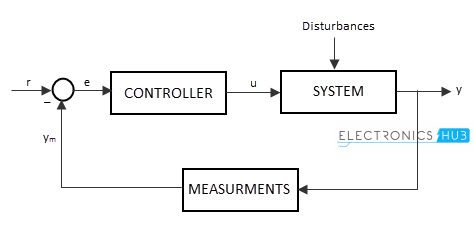
A block diagram of this system is shown in Fig 11 You have been given the task of designing the compensation Begin by considering a proportional control law D c (s) = K Figure 11 Control system for Problem 633 (a) Use MATLAB to draw a Bode plot of the openloop system for D c (s) = K = 1The block diagram of this control system is shown below In the following diagram, we can see two blocks, one is a controller block and another one is a controlled process block Basing on the output requirement, the input is given to the controller of the system The controller receives the input signal and generates the control signal and itK Webb MAE 4421 3 Block Diagrams In the introductory section we saw examples of block diagrams to represent systems, eg Block diagrams consist of Blocks–these represent subsystems – typically modeled by, and labeled with, a transfer function Signals– inputs and outputs of blocks –signal direction indicated by


Q Tbn And9gcsclj5 Hy3qiocvwj6xbeocmi9k8opqi2qlvzukuxibwcvtzvbm Usqp Cau


Block Diagram Control System Block Diagram Diagram Process Flow Diagram
Interactive Block Diagrams Our Interactive Block Diagram tool is as easy to use as 1, 2, 3 With a vast variety of diagrams to choose from, you are able to experience the full breadth of the ON Semiconductor product portfolio in a clear, concise mapped out system level block diagramThe openloop control system block diagram is shown below In the following diagram, the input can be given to the control system so that the required output can be obtained However, this obtained output cannot be considered using this system for additional reference inputA block diagram makes a very efficient representation of the overall running of a computer system It displays the necessary processes needed to get the desired output from a computer from the input you feed into at the start In the diagram below, the control unit (CU) and the arithmetic & logic unit (ALU) make up the Central Processing Unit (CPU) in a computer It is the brain cum the heart
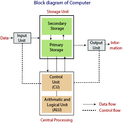


Block Diagram Of Computer Tutorial And Example


Block Diagram Safe Home Security System Group
A block diagram of a system is a pictorial representation of the functions performed by each component and of the flow of signals The elements of a block diagram are block, branch point and summing point Block In a block diagram all system variables are linked to each other through functional blocksWhat is Basic Block Diagram of Computer System Block Diagram of Computer System The Computer system consists of mainly three types that are central processing unit (CPU),Input Devices, and Output DevicesThe Central processing unit (CPU) again consists of ALU (Arithmetic Logic Unit) and Control Unit The set of instruction is presented to the computer in the form of raw data which is entered through input devices such as keyboard or mouse


Navigation Systems Block Diagram Electronic Products


System Algebra And Block Diagram
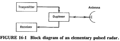


Basic Radar System Block Diagram Fundamentals Frequencies And Powers
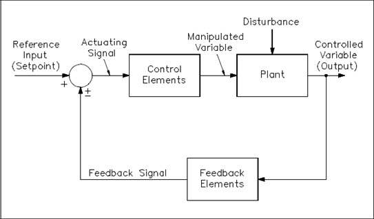


What Is Block Diagram Anything You Need To Know Edrawmax Online


What Is A Block Diagram Of An Embedded System Quora
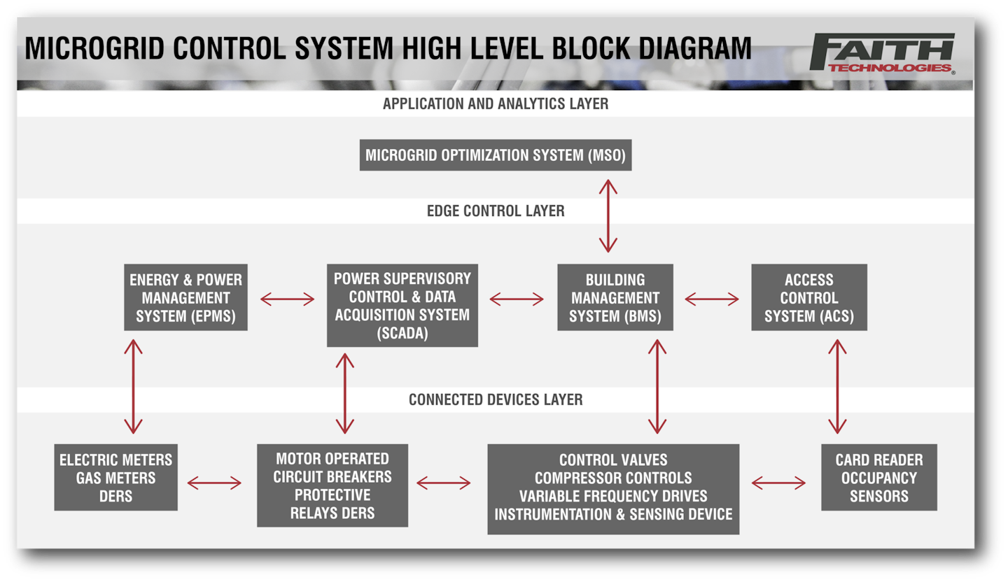


Microgrids And Connected Buildings Ec M
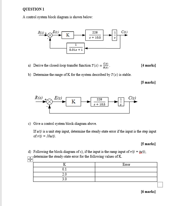


Solved Question 1 A Control System Block Diagram Is Shown Chegg Com


Block Diagram Control System Diagram Block Diagram Control System
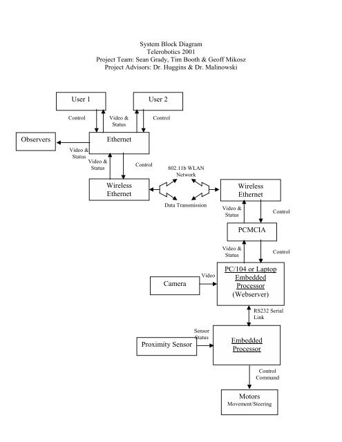


System Block Diagram


Block Diagram Learn About Block Diagrams See Examples
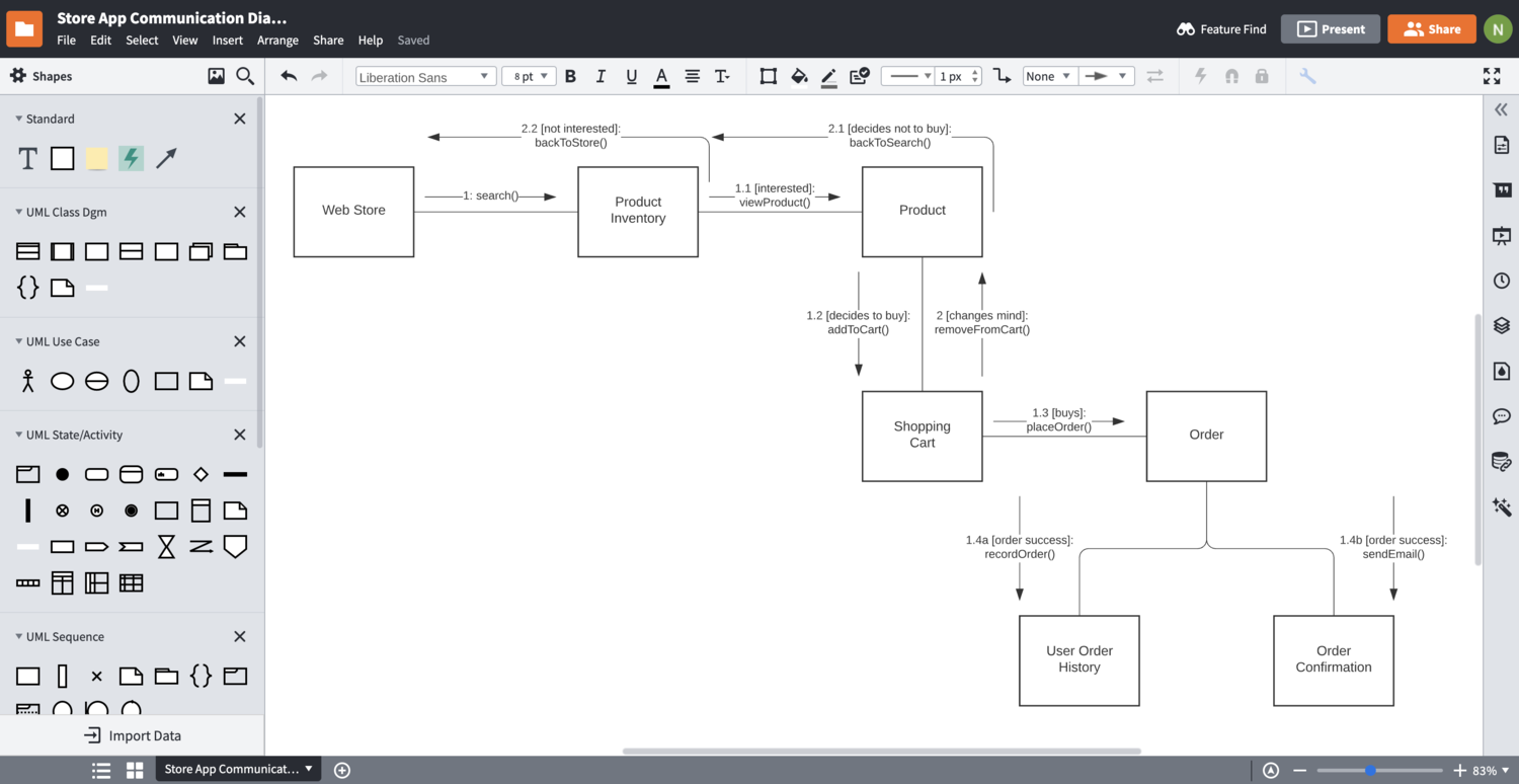


Block Diagram Maker Lucidchart


Block Diagrams Of Control System Electrical4u


Peak Current Mode System Block Diagram Developer Help


Reliasoft Blueprint Blocksim System Block Diagram Wilde Analysis Ltd


Central Hvac System Block Diagram Design Solutions Stmicroelectronics
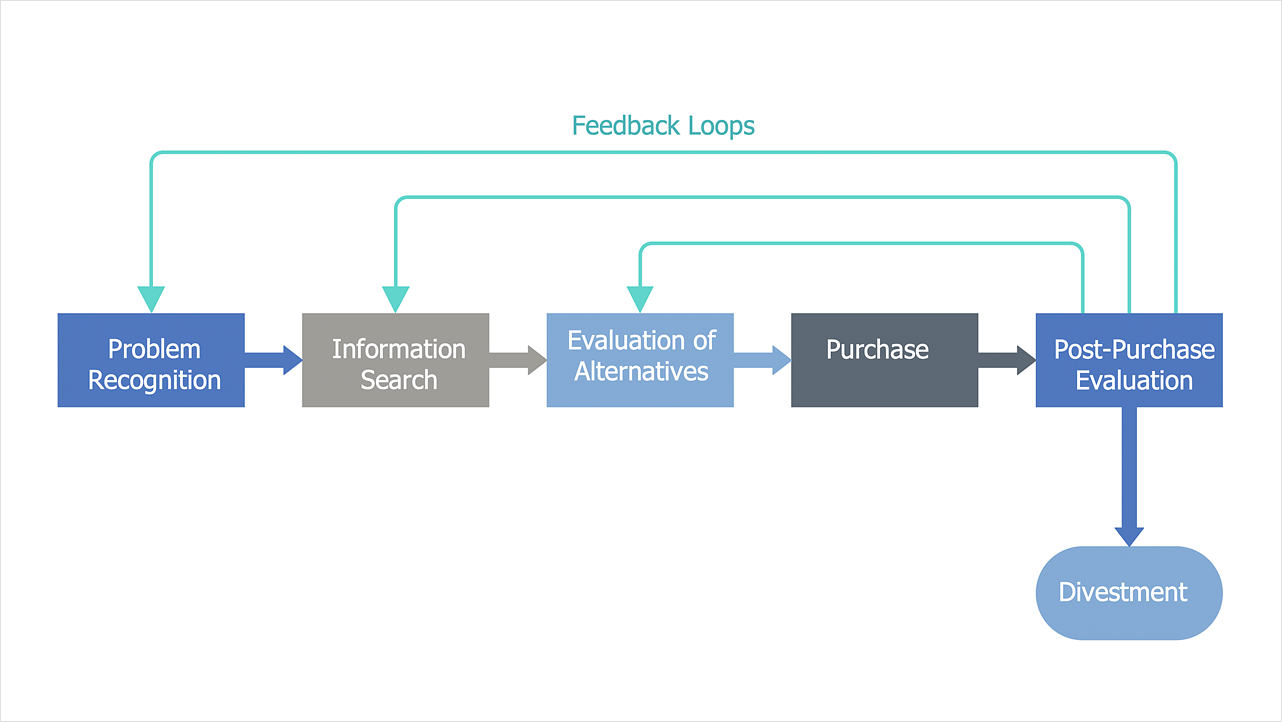


Block Diagrams How To Draw A Block Diagram Business Diagrams Org Charts With Conceptdraw Diagram Information System Block Diagram


Ict System Block Diagram Jack Oldham Y12 Ict
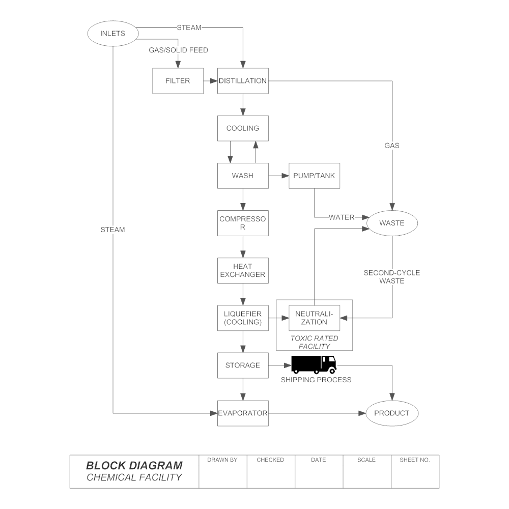


What Is Block Diagram Anything You Need To Know Edrawmax Online


Communication System Block Diagram Electronx


Computer System Block Diagram Computer Fundamentals


Eye01usmrw Cctv System Block Diagram 4 Eyecon


Ultimate Block Diagram Tutorial Explain With Examples
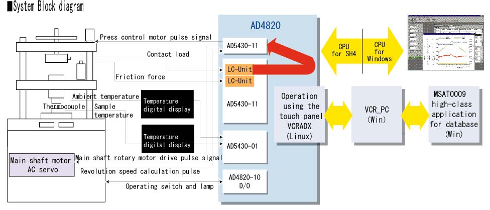


System Block Diagram
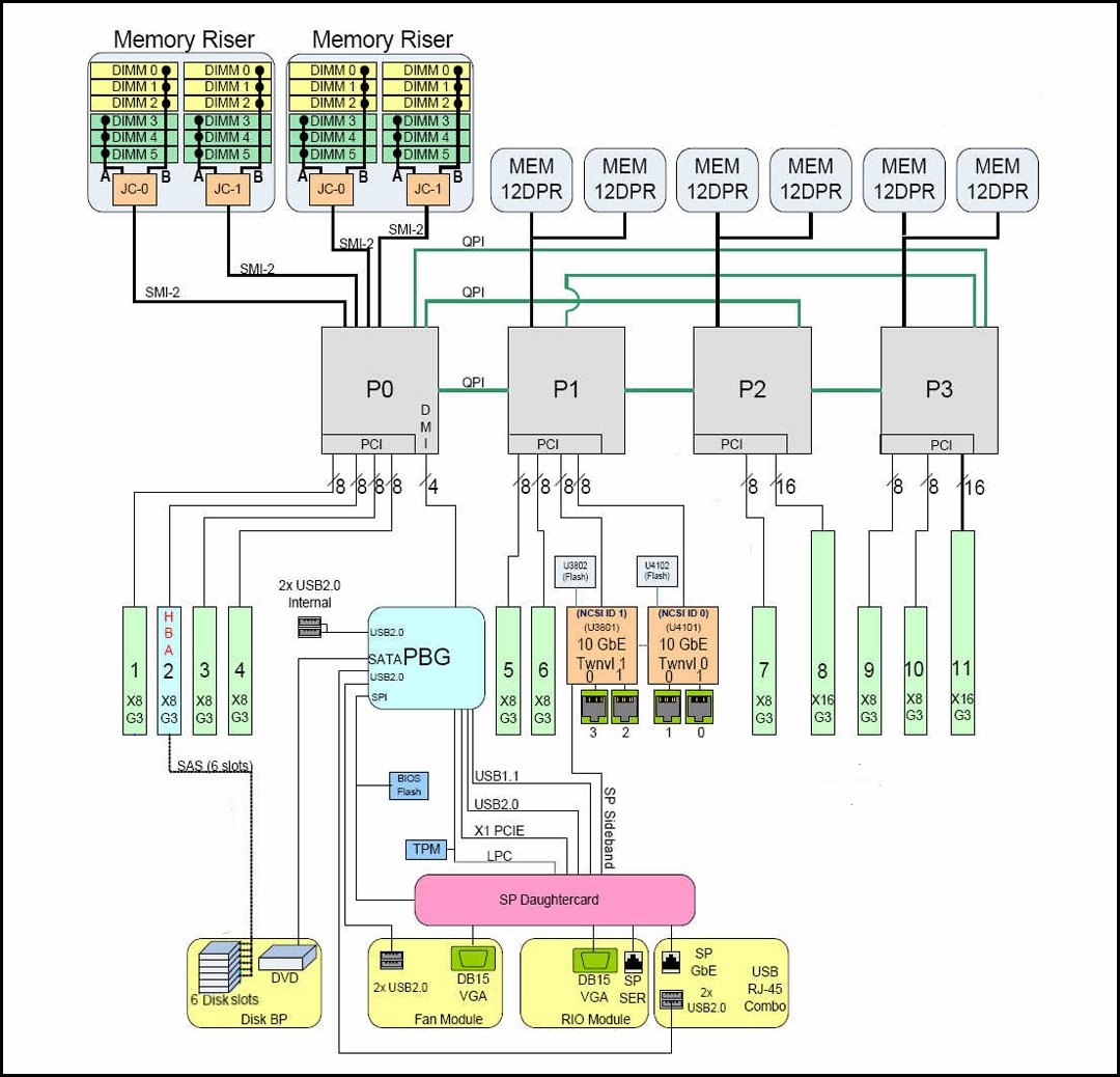


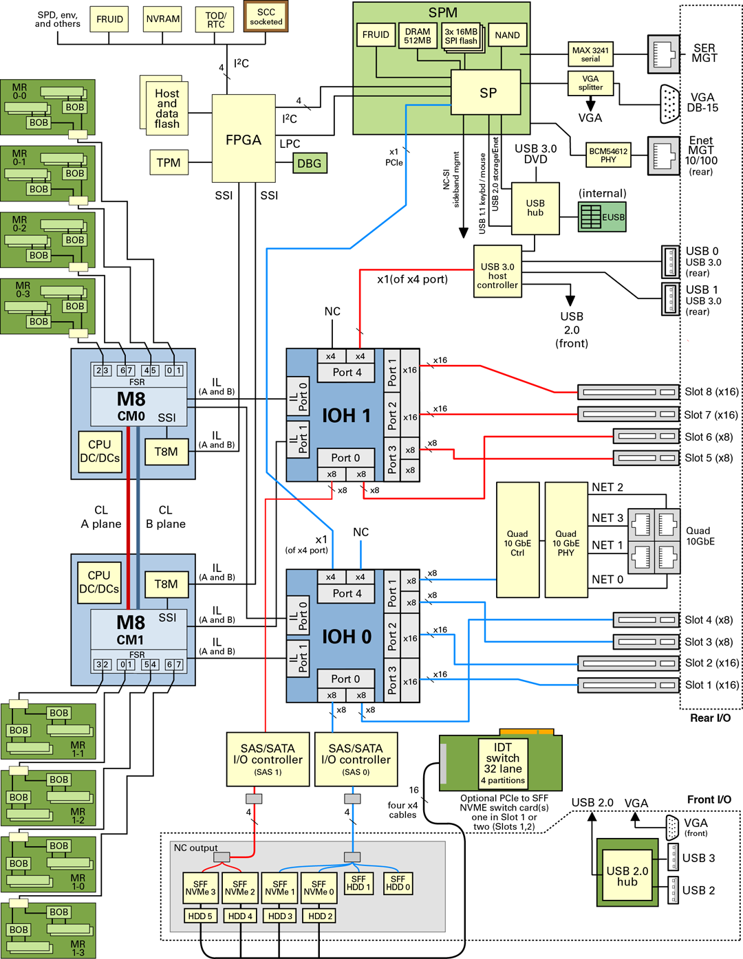
System Block Diagrams Sun Server X4 4 Service Manual


Block Diagrams Electronics Club


Using Block Diagrams As A System Design Language Part 1 Embedded Com


System Block Diagram An Overview Sciencedirect Topics


Basic Block Diagram Of Communication System Polytechnic Hub


Information System Block Diagram Download Scientific Diagram


System Block Diagram An Overview Sciencedirect Topics


Basic Block Diagram Of Analog Communication System Ece4uplp
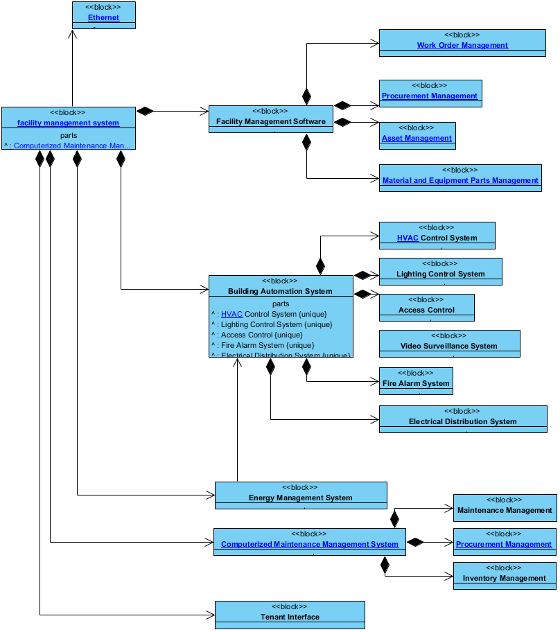


Block Definition Diagram Facility Management System Block Definition Diagram
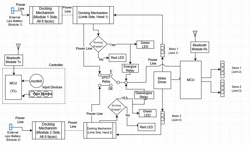


Limbi Spring 19 System Block Diagram Iterations Arxterra


Electrical System Block Diagram Electrical z


3


Edge


System Block Diagram Ieee Computer Society



Position Control System Block Diagram


Server Block Diagram Sparc T8 2 Server Service Manual
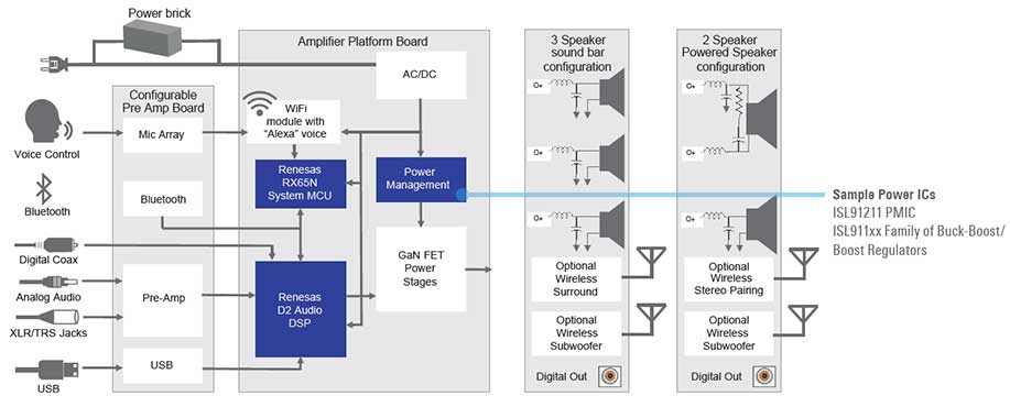


3 In 1 Audio System Block Diagram Renesas


The Basics Of Process Control Diagrams Technology Transfer Services


System Block Diagram An Overview Sciencedirect Topics
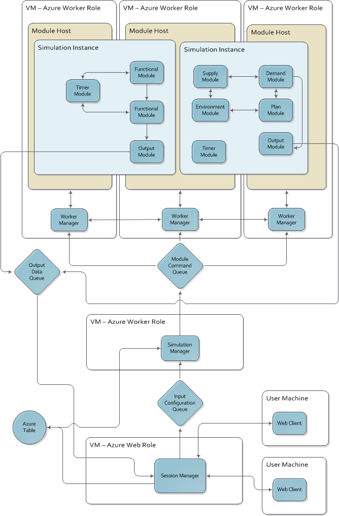


System Block Diagrams


Block Diagram Of Computer Tutorialsmate


Block Diagram Of The Temperature Monitoring System Download Scientific Diagram


Block Diagram Matlab Simulink


Block Diagram Learn About Block Diagrams See Examples


Instrumentation System Block Diagram


Falcom Technology Eoc System Block Diagram


System Block Diagram And Event Timeline Note That Information Exchange Download Scientific Diagram


Q Tbn And9gctxagvo2ivwi5toyngxx5tguieubfbjqqhgfcwmisogzl Dzy4j Usqp Cau


Feedback Control System Block Diagram Bani Instind 23
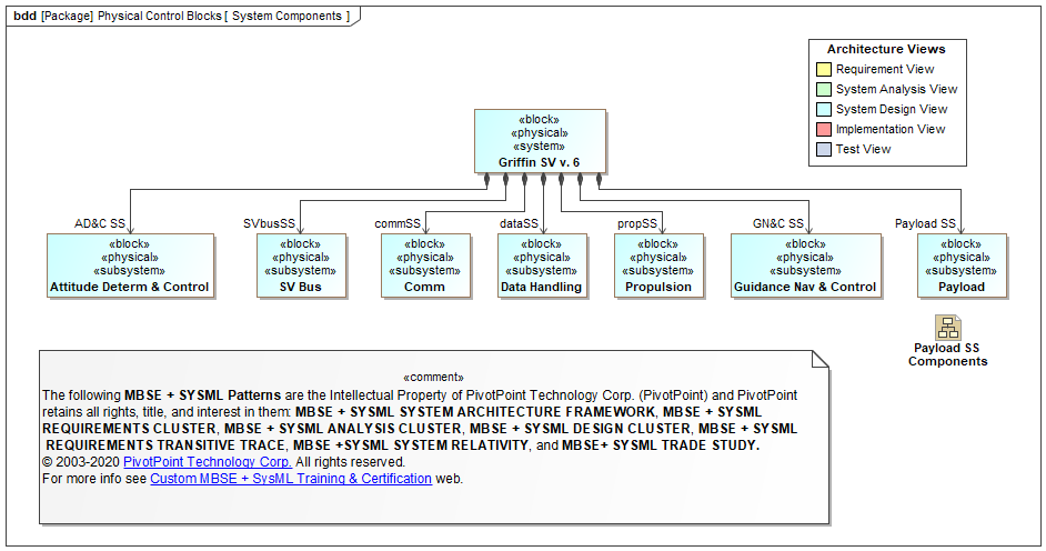


Sysml Faq What Is A Block Definition Diagram d


Basic Communication System Applications Block Diagram


Block Diagram For Control Thin Film Coating System Shinmaywa Industries Ltd


Electronic System


Block Diagram Wikipedia


Block Definition Diagram Access Control Block Definition Diagram


What Is A Block Diagram Knolwledge Base


Block Diagrams And Introduction To Control Systems Springerlink


File Apollo Block I Guidance System Block Diagram Png Wikimedia Commons


Control Systems Block Diagram Reduction Tutorialspoint


Process Control System Block Diagram Distributed Control Systems Dcs Instrumentation Forum


Block Diagram Of Embedded System Download Scientific Diagram


Control Systems Block Diagrams Tutorialspoint


Facebook Ocp Delta Lake Cooper Lake 1s System Block Diagram Servethehome


System Dynamics And Control Module 13b Block Diagram Reduction Youtube


Edge


Q Tbn And9gctfj4adkfjzvgr334mldl3ddbjw0n0mkhqzvrepjaurgxq1frte Usqp Cau


Ece5 Lecture 8 3 Block Diagrams Feedback Systems Youtube


Understanding Electronics Block Diagrams With Example Eleccircuit Com


Block Diagram Of Process Control System Polytechnic Hub
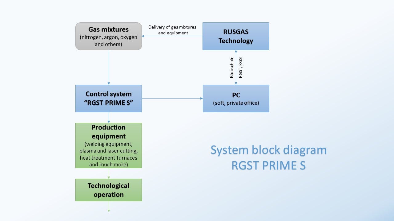


System Block Diagram The Development Of This System In The By Rusgas Io Medium


Automotive Braking System Block Diagram Electronic Products
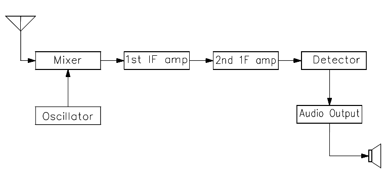


Block Diagram Instrumentation Tools


Automotive Ivi Toshiba Electronic Devices Storage Corporation Europe Emea


Data Acquisition System Block Diagram Your Electrical Guide
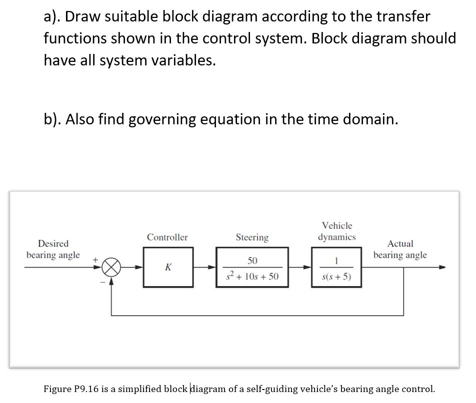


Solved A Draw Suitable Block Diagram According To The T Chegg Com


Block Diagram


System Algebra And Block Diagram


コメント
コメントを投稿